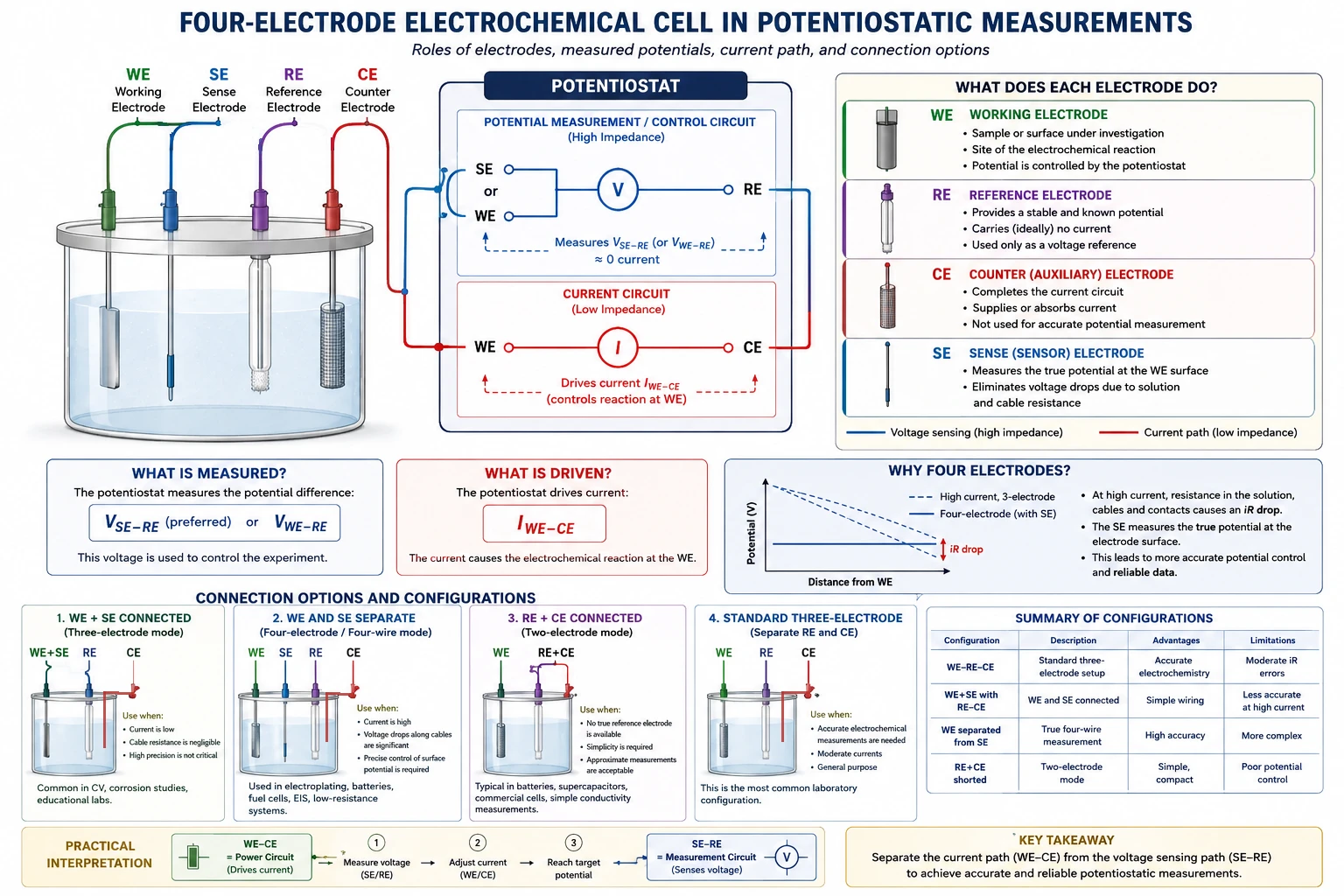
Four-Electrode Electrochemical Cell in Potentiostatic Measurements
Introduction
Modern electrochemical measurements are usually performed using a potentiostat/galvanostat connected to a multi-electrode electrochemical cell.
The standard laboratory configuration is often called a four-electrode setup, although electrically it is based on two separate circuits:
- Potential-control (voltage-sensing) circuit
- Current-carrying circuit
Understanding the role of each electrode is essential for reliable measurements, especially in:
- corrosion studies,
- electroplating,
- batteries and fuel cells,
- electrochemical impedance spectroscopy (EIS),
- electrocatalysis,
- semiconductor electrochemistry.
The four electrodes are:
| Abbreviation | Name | Main Function |
|---|---|---|
| WE | Working Electrode | Object/sample under investigation |
| RE | Reference Electrode | Stable voltage reference |
| CE | Counter (Auxiliary) Electrode | Carries balancing current |
| SE | Sense Electrode (Sensor) | Measures true potential directly at the WE |
1. Working Electrode (WE)
The working electrode is the central element of the experiment.
It is the electrode:
- whose electrochemical behavior is being studied,
- whose potential is controlled,
- and through which the electrochemical reaction of interest occurs.
Examples:
- a steel sample in corrosion testing,
- a battery electrode,
- a catalytic surface,
- a semiconductor wafer,
- an electroplated component.
At the WE, reactions such as:
- oxidation,
- reduction,
- dissolution,
- deposition,
- adsorption, occur.
The potentiostat attempts to maintain the desired potential of the WE relative to the RE.
2. Reference Electrode (RE)
The reference electrode provides a stable and well-defined electrochemical potential.
Typical examples:
- Ag/AgCl,
- saturated calomel electrode (SCE),
- Hg/HgSO₄,
- reversible hydrogen electrode (RHE).
The RE ideally:
- carries almost no current,
- remains chemically stable,
- provides a constant reference voltage.
The potentiostat continuously measures:
using a very high-impedance input so that essentially no current flows through the RE.
This is critical because current flowing through the RE would polarize it and destroy its stability.
3. Counter Electrode (CE)
The counter electrode (also called auxiliary electrode) completes the current circuit.
Its role is:
- to supply or absorb the current required by the WE reaction.
The CE is usually:
- chemically inert,
- large in surface area,
- made from Pt, graphite, titanium, etc.
The potentiostat drives current between:
- WE and CE
in order to maintain the requested potential between:
- WE and RE.
Important:
- the CE is not used for accurate potential measurement,
- voltage drops near the CE are usually irrelevant,
- polarization of the CE is acceptable as long as it does not limit the experiment.
4. Sense Electrode (SE)
The sense electrode (sometimes called “sense lead” or “sensor electrode”) is used to measure the true local potential directly at the working electrode surface.
Its purpose is mainly to eliminate errors caused by:
- solution resistance,
- cable resistance,
- contact resistance,
- high current operation.
This is especially important in:
- high-current electroplating,
- batteries,
- fuel cells,
- conductivity measurements,
- EIS,
- low-resistance systems.
The SE is connected very close to the WE surface, often physically adjacent to it.
The Two Separate Circuits
A potentiostat internally contains two different electrical loops.
A. Potential Measurement / Control Circuit
This circuit measures:
or, in four-wire mode:
This is a high-impedance voltage measurement circuit.
Characteristics:
- almost no current flows,
- used only for sensing voltage,
- determines whether the desired potential is reached.
B. Current Circuit
This circuit drives current between:
The potentiostat adjusts this current automatically until the measured voltage reaches the target value.
The measured current reported by the instrument is usually:
Why Four Electrodes?
In low-current systems, cable and solution resistance may be negligible.
But at high current:
where:
- (i) = current,
- (R) = unwanted resistance.
This creates significant errors.
The four-electrode configuration separates:
- current carrying, from
- voltage sensing.
This is analogous to a Kelvin four-wire measurement used in electrical metrology.
WE + SE Connection
In many experiments, the WE and SE terminals are physically connected together.
This is done when:
- current is relatively low,
- cable resistance is negligible,
- the WE is physically small,
- high precision is not required.
In that case:
and the instrument behaves effectively as a standard three-electrode potentiostat.
This configuration is common in:
- routine cyclic voltammetry,
- corrosion measurements,
- educational laboratories,
- standard electrochemical cells.
Separate WE and SE Connections
WE and SE are kept separate when:
- current is high,
- voltage drops along cables are significant,
- precise surface potential control is required.
Examples:
- industrial electroplating,
- battery testing,
- fuel cells,
- high-current polarization,
- impedance spectroscopy.
In this case:
- WE carries current,
- SE senses voltage locally at the sample.
Thus the potentiostat compensates for parasitic voltage drops automatically.
RE + CE Connection
Sometimes the RE and CE are intentionally shorted together.
This converts the system into a two-electrode configuration.
This is done when:
- a true reference electrode is unavailable,
- simplicity is preferred,
- approximate measurements are acceptable,
- the device itself already contains only two terminals.
Typical examples:
- batteries,
- supercapacitors,
- commercial cells,
- simple conductivity measurements,
- some impedance measurements.
However, in this mode:
- the counter electrode is polarized,
- the reference potential is no longer stable,
- measured potentials become less accurate.
Therefore:
- quantitative electrode potential measurements become difficult or impossible.
Comparison of Configurations
| Configuration | Description | Advantages | Limitations |
|---|---|---|---|
| WE–RE–CE | Standard three-electrode setup | Accurate electrochemistry | Moderate IR errors |
| WE+SE with RE–CE | Common practical setup | Simple wiring | Less accurate at high current |
| WE separated from SE | True four-wire measurement | High accuracy | More complex |
| RE+CE shorted | Two-electrode mode | Simple, compact | Poor potential control |
Practical Interpretation
A useful conceptual picture is:
- WE–CE → “power circuit”
- SE–RE → “measurement circuit”
The potentiostat continuously:
- measures voltage using SE/RE,
- adjusts current through WE/CE,
- until the target condition is satisfied.
Typical Experimental Choices
| Application | Recommended Configuration |
|---|---|
| Cyclic voltammetry | WE+SE, separate RE and CE |
| Corrosion testing | WE+SE, separate RE and CE |
| Electroplating at high current | Separate WE and SE |
| Battery testing | Two-electrode or four-electrode |
| EIS of low-impedance systems | Separate WE and SE |
| Fuel cells | Separate WE and SE |
Summary
The four electrodes in a potentiostatic experiment serve fundamentally different purposes:
| Electrode | Function |
|---|---|
| WE | Site of electrochemical reaction |
| RE | Stable voltage reference |
| CE | Current-carrying auxiliary electrode |
| SE | Local voltage sensing near WE |
The potentiostat operates using:
- a current loop (WE–CE),
- and a voltage sensing loop (SE–RE or WE–RE).
Connecting:
- WE + SE simplifies the setup and is adequate for many routine experiments.
- RE + CE converts the system into a simpler but less accurate two-electrode configuration.
Proper selection of configuration depends mainly on:
- required accuracy,
- current magnitude,
- solution resistance,
- and experimental goals.
In routine corrosion EIS of metallic plates in aqueous electrolytes, a separate sense electrode is usually unnecessary. The sense lead is normally connected to the working electrode terminal or directly to the sample. Accurate potential sensing is achieved by placing the reference electrode, preferably through a Luggin capillary, close to the working electrode surface. A separate SE becomes useful mainly in high-current, low-impedance, large-area, or four-wire/Kelvin-type measurements where voltage drops in leads, contacts, or the specimen itself are non-negligible.